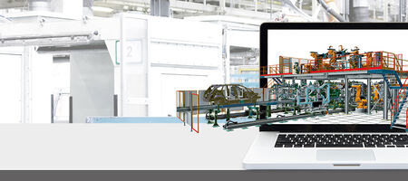
Basis for the digital twin - modelling for virtual commissioning
In virtual commissioning (VIBN), the behaviour of a planned machine or system is simulated using a digital twin. The creation of the virtual model required for this is primarily subject to the following requirements: it must not be complex or time-consuming and it should be possible to use existing data sources for generation that is as automated as possible. The use of simulation software offers plenty of scope for direct and rapid efficiency improvements.
There is a general trend towards increasingly complex functional sequences in mechanical and plant engineering. The virtual testing and optimisation of the entire control software - be it for PLC, robotics or master control - in the run-up to commissioning is of great importance. The aim of a VIBN is to detect and rectify faults at an early stage and to ensure the interaction between the plant mechanics and control software. This process moves away from the sequential workflows of most engineering organisations and changes to parallel processing in order to save processing time and costs.
Abstraction and modelling depth
The VIBN is based on the use of simulation models that abstract the real behaviour of the system in order to deliver results that are as close to reality as possible. The choice of modelling depth depends on the system to be simulated and must inevitably be different in an extensive intralogistics system with 1,000 drives than in a processing machine with complex mechanical assemblies, a high density of sensors and actuators as well as parallel, small-scale processing steps. The modelling depth has no influence on the connection of the model to the control system via software in the loop (SIL) or hardware in the loop (HIL). A high level of detail increases the effort required to create the model, which is why the following guideline should be followed when creating the model: ‘As precise as necessary, as idealised as possible’. A VIBN will not be able to replace real commissioning, as there are still activities that can only be carried out on the real plant. However, a VIBN secures the engineering and programming, shortens the project time, reduces commissioning costs, achieves higher plant availability throughout the entire commissioning process and makes a decisive contribution to simplifying it.
The modelling framework
As a rule, the data from the mechanical design forms the basis for modelling. Depending on the engineering process, data is available in different applications and of varying quality. If usable CAD data is only available at an advanced engineering stage, it is important to be able to work with idealised models in order to ensure that software development can start at an early stage. It should also be possible to use other data sources - such as Excel, databases, Visio layouts - as a basis for modelling in order to obtain a reliable model at an early stage. The primary goal must be to create the plant model as automatically as possible from the existing data. It helps enormously if the simulation solution used can be easily adapted to a company's data structures and offers open interfaces. There are solutions that have an application programming interface (API) that enables the model to be created automatically. Using embedded macros in the source system (CAD, Excel, Visio, etc.), all elements are analysed and transferred to the simulation with the available information via the API. If data is changed in the simulation model, it can also be transferred back to the source system bidirectionally via the same interface.
Learning to walk with behavioural models
The task of the behaviour model is to simulate the logical and temporal behaviour of the real operating equipment in relation to the connected control systems. The models primarily consist of individual simulation modules of the equipment used in the real system - such as drives, valve terminals and readers. It is best if the simulation solution contains its own, modifiable library of modules and also offers the option of creating your own behaviour models. This starts with simple scripts in which state machines for simple I/O logics are realised, through to the possibility of developing your own dynamic link libraries (DLL), which not only contain functionality but also complete user interfaces. Software manufacturers often offer modelling as a service. It would also be desirable for the manufacturers of automation components to provide behavioural models that can be embedded directly in the simulation solution. There are already manufacturers who, for example, provide behaviour models for drives or gripper systems for integration into the simulation platform. If libraries of behavioural models already exist in an existing simulation solution, it is advantageous if these can also be used in other simulation environments in the form of a co-simulation.
Linking the model with PLC, subsystems and peripherals
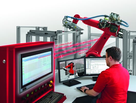
The providers of simulation software take different approaches when coupling VIBN applications with the control and subsystems as well as the peripherals - for example as HIL or SIL. On the one hand, this depends on the expected performance: While signal exchange with a simulation model in the range of 10 to 20 ms may be sufficient in logistics, 1 ms may still be too slow for an NC machine. On the other hand, how the peripherals are to be integrated into the simulation environment must also be taken into account. Communication with the systems can take place on the basis of a native connection - e.g. via Ethernet based on TCP/IP - but also via open communication standards such as OPC UA. In order to make data transmission via Ethernet real-time capable, PLC manufacturers are currently implementing OPC UA over TSN in pilot projects, which enables cycle times of less than 1 ms. A flexible connection to communication interfaces will therefore play a major role in future system environments. Various options are available for simulating and connecting fieldbus devices. There are communication boxes that simulate fieldbus devices so that they are available for the PLC, including safety signals. The simulation is so realistic that there is no difference between the simulated and real devices for the PLC and the simulated software can be used directly during real commissioning without corrections or adjustments.
Function test before starting
Over the course of an engineering process, the detailing of a digital model can be further improved and refined with additional data, which is often only available in later project phases. Data or concepts that change during the engineering phase can also be transferred to the model flexibly and without having to rebuild it. Once all the required information has been integrated into the model, a final test run is carried out. The PLC and robot programmers perform a final check of all virtual inputs/outputs and the individual functions are also called up again manually. If the test run fulfils expectations, the VIBN can begin. The aim is to test the processes and functions of the system on the digital twin without getting lost in details that have to be tested on the real system anyway. Incidentally, the model created is not only used for the VIBN, but can also be used later for optimisation, conversion or training purposes.
Author: Werner Pospiech, Sales Manager Industrial Software (fe.screen-sim) at F.EE GmbH

Your personal contact person – for more clearness
You are a project or department manager and are faced with the question of how to set up a digital twin for your project? We would be happy to talk to you personally about your requirements, the time frame, the possible project approach and give you an initial cost estimate.